Read about the unique opportunity for geometry analysis, fabrication, and the resulting gallery installation as initially reported on the Tocci Blog...
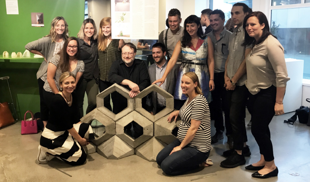
Image Credit: Jamie Farrell
On July 27th, an opening reception was held for Autodesk’s BUILDing Forward exhibit at the Boston Society of Architects. This exhibit celebrates digital craft in the greater Boston community and highlights the research projects made possible by the Autodesk BUILDSpace — a state-of-the-art research and development facility in the Design Center.
Tocci partnered with Sasaki Associates to research and develop a prototype called WinterLight, a proposal for a temporary winter pavilion for the Rose Kennedy Greenway. Currently in the early design phase, WinterLight is a warming hut designed to encourage activation of the city’s public realm during the winter months. The structure is a semi-dome with strategic openings in customized masonry blocks, designed to shield visitors from winter winds while they enjoy the warmth of an interior fire pit. The final location of the pavilion will be located in Boston: the site is to be determined.

Image Credit: Lucca Townsend, Sasaki Associates
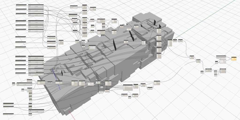
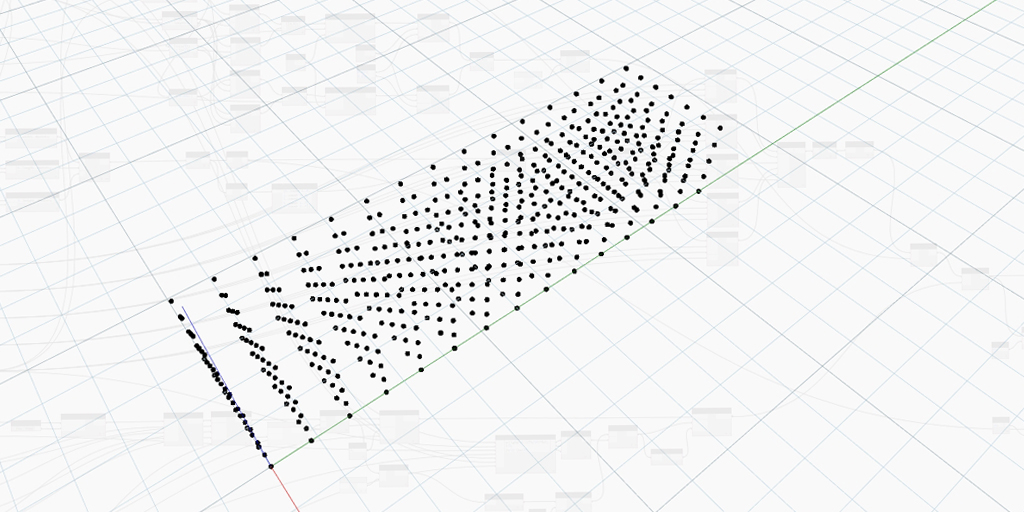
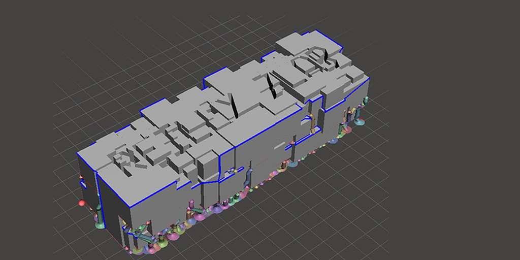
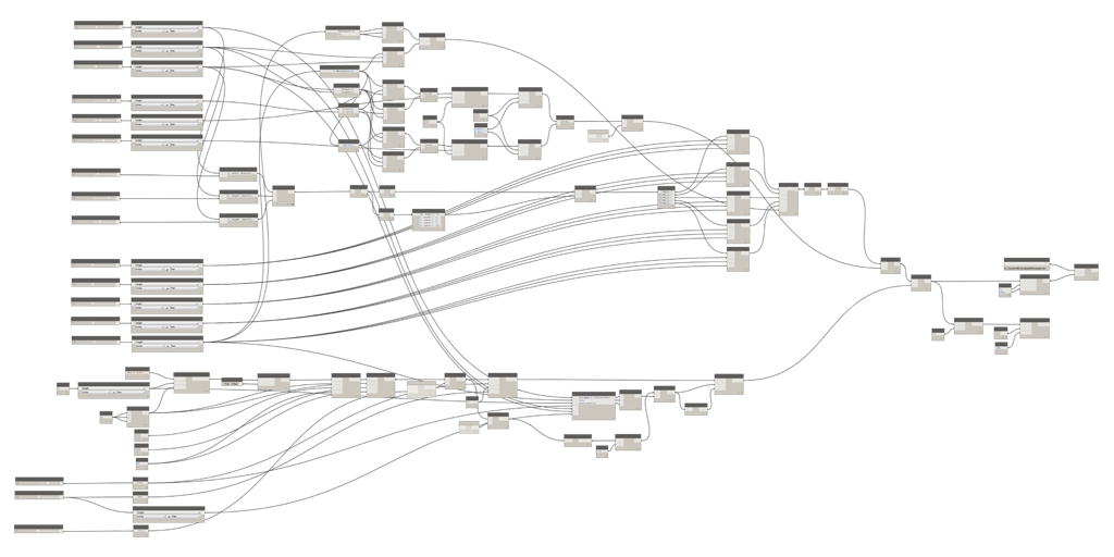
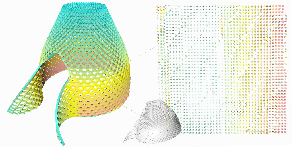
This project required extensive computational design from Sasaki staff to strike a balance between desired aesthetic and regularity of the blocks. Tocci’s role was to assist with geometry analysis and support the design process through construction feasibility studies. With each new design iteration, we utilized Dynamo Studio to extract total pavilion dimensions, overall block quantities, block sizes, repeatable types, total volume, total weight, and other metrics.

Image Credit: Lucca Townsend, Sasaki Associates
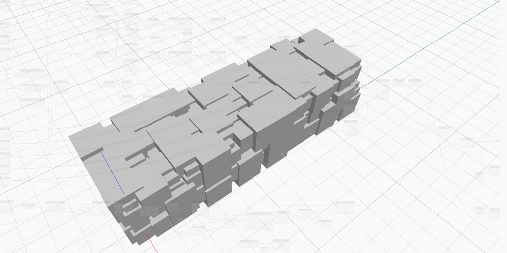
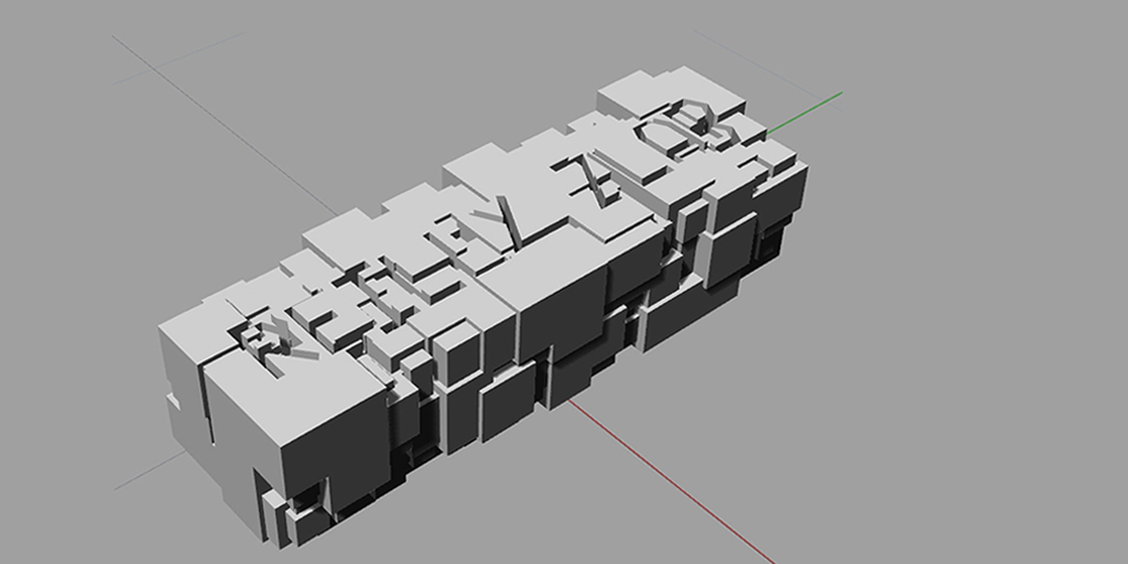
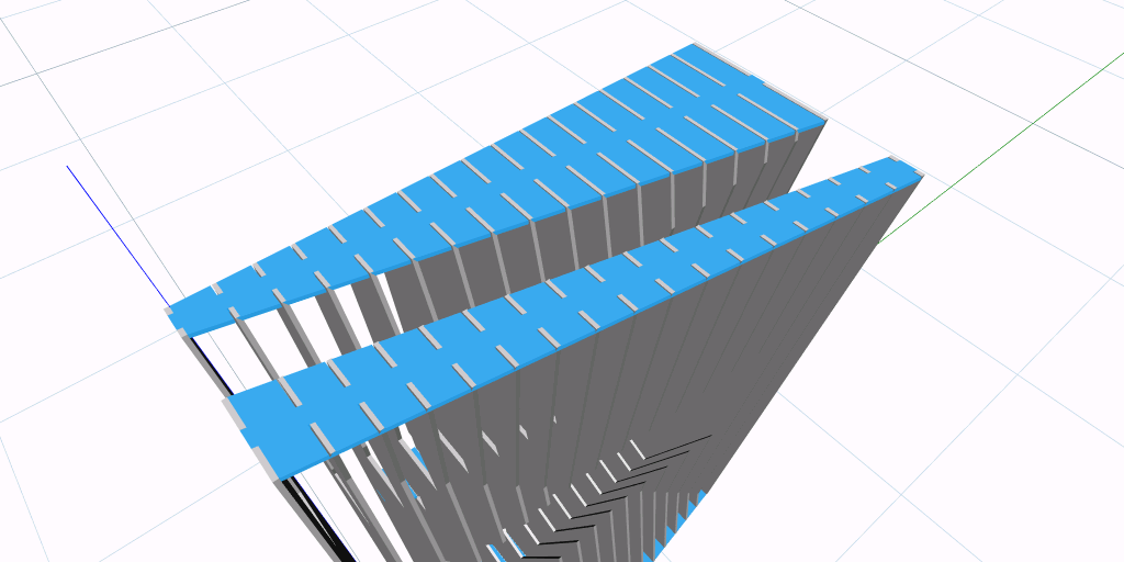
The BUILDing Forward exhibit provided the perfect opportunity to experiment with fabrication methods and materials for producing the unique geometry of the blocks. Sasaki chose a section of nine blocks comprised of five unique types from the overall pavilion to demonstrate scale and geometric variation. They first generated a digital model of the composition, and then processed the individual shapes into toolpaths for cutting profiles from Medium Density Fiberboard (MDF) using a Computer Numeric Control (CNC) three-axis router. They continued to cut an ingenious system of holes into the MDF sheets, lining up each piece using threaded rod. This created a negative form of each block shape for pouring concrete. Each concrete form also incorporated removable sections and a hole at the top for concrete. At this time, they sanded and coated the interior surfaces of the forms with an epoxy sealer to facilitate the release of concrete.

To prep for pouring, we disassembled the forms to coat the interior surfaces with form release. They were then reassembled on the threaded rod guides and tightened using nuts and washers.

We blended Portland cement and sand silica to create a concrete mixture that could support the compressed weight of the stacked blocks and maintain a smooth, gallery-quality finish. As each five-gallon-bucketful of concrete was poured through the top, a team tapped the sides of the forms, agitating the mixture and forcing trapped air bubbles to the surface.

Image Credit: Christine Dunn, Sasaki Associates
At times, the form release did not properly work, forcing us to pry the blocks from their forms.

Rotating shifts of the Sasaki-Tocci team spent a week to producing the prototype, as each block required 24 hours to cure. With one last round of chiseling and sanding, all nine blocks were ready for their BSA Space debut.

The opening reception was well attended. It was inspiring to see so many creative projects coming out of the BUILDSpace and local AEC community. BUILDing Forward will be on display at the BSA until October 5th, 2017 if you would like to see our work and all the other excellent projects.
Stay tuned for more as the WinterLight project evolves into a full-scale realization.
Check out this Sasaki blog post about the BUILDing Forward event for even more information.