Dynamo-litia Boston - September 2017

For this month's installment of the Dynamo-litia, we celebrated the 2 YEAR ANNIVERSARY of the user group's existence!

Dynamolitia_2yr-anniversary_FINAL.gif

plus...

Dynamo-litia_Meeting 12_marketing_FINAL.jpg

Comparing Computational Approaches / Dynamo-litia Turns 2!
The AEC industry is currently experiencing a surge in technology with new tools emerging every day to produce time-honored deliverables in unique ways. What has long been considered "industry standard" software is being aided and at times replaced by the "right tool for the job".

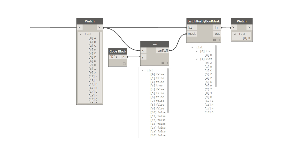
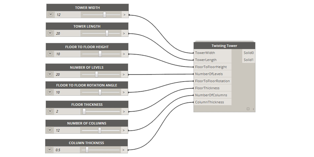
Please join Ilaria Giardiello Assoc. AIA and Kyle Martin Assoc. AIA as they lead a live demonstration of the spectrum of computational approaches that can be used to accomplish the same task, including: Dynamo, Custom Nodes, Design Script Syntax, and Python. Today there are many ways to get to the same end result; this session seeks to illuminate why it is important to be aware of the tools at your disposable and play to your strengths.

Also this month is the 2 Year Anniversary of the Dynamo-litia Boston user group! To celebrate we will be recapping the past year as well as highlighting a flurry of events happening this Fall. This is one session you won't want to miss.


When: September 27, 2017
Where: BSA Space - Boston

More information at the Boston Society of Architects .
Presentation slides and datasets can be downloaded HERE .

Dynamo-litia Boston Turns 1!

This week the Dynamo-litia Boston celebrated it's One Year Anniversary. To celebrate, I used Dynamo to generate a virtual birthday cake.

Here are some of the highlights of the first year:

First session: September 21, 2015

7 Presentations:

  1. Introduction to Dynamo
  2. Dynamo for Production
  3. Dynamo and the Evolution of BIM
  4. Dynamo for All
  5. Dynamo and the Zen of Data Flow
  6. Work Smarter Not Harder
  7. Bringing Engineers & Architects Together Through Digital Design

1 Workshop:
Revit parameter export
Panelized surface & analysis


Did you know there is an entire Vimeo album devoted to the Dynamo-litia?

Dynamo-litia Boston Album

6 videos
1,777 Plays
51 Finishes
Average time per view: 34m,06s

Top 10 Countries:
US, UK, Spain, Canada, Brazil, Australia, Netherlands, Italy, Singapore, Germany

Lastly, this year would not have been possible without the contributions of many. Special thanks to:

Boston Society of Architects:
Conor MacDonald
Sara Garber
Revit User Group

Autodesk - Dynamo Team

Shepley Bulfinch

Speakers:
Zach Kron - Autodesk
Kevin Tracy - NBBJ
Christina Tully – Shepley Bulfinch
Masha Pekurovsky – Perkins Eastman
Eric Rudisaile - Microdesk
Timon Hazell - Silman

Most importantly, the Boston AEC Community! Looking forward to future sharing and collaboration.

Dynamo-litia Boston - September 2016

This installment of Dynamo-litia featured Timon Hazell, Sr. BIM Engineer at Silman (Washington DC).

Bringing Engineers and Architects Together Through Digital Design
Design changes that took weeks to coordinate are now happening in hours. We are now able to create new iterations of complex designs in seconds. This speed has its benefits, but it also adds complexity to current collaboration practices. How can we work better as a single design team? How can we use conceptual abstract models to generate documentation models? How can we model non-planar framing directly in Revit? You know the answer to many of these involves Dynamo! Join us as Timon Hazell from Silman shares his experiences and talks through a few case studies using Revit, Rhino, Dynamo and Grasshopper.

When: September 22, 2016
Where: Shepley Bulfinch - Boston

More information at the Boston Society of Architects.

Due to A/V difficulties, a few portions of the presentation did not make the video. To follow along AND see upcoming announcements, make sure to download the presentation slides HERE.

Dynamo-litia Boston - April 2016

Dynamo is a proven tool for modifying Revit information and automating repetitive tasks, yet figuring out where to get started can be an intimidating process. Please join us for the first in a two part series on how to begin using Dynamo. We will focus on what it is useful for and highlight several introductory workflows that can be understood with everyday Revit knowledge. Since Dynamo is new to the majority of the local AEC community, we will discuss how regular project challenges can be opportunities to explore principles and grow knowledge. For those who are already experts of other software platforms, see how Dynamo has made the process of transferring geometry and information easier than ever before.

The video and presentation slides are available HERE.

More information at the Boston Society of Architects.

Common Selection Methods Using Dynamo


The Dynamo visual programming add-in for Revit enables advanced information gathering, rapid model changes, and repetitive task automation previously not available with the out of the box tools. Working with robust Building Information Models often requires surgical list management -- the act of gathering, filtering, re-structuring, sorting, or otherwise altering clusters of data or information. Of all possible list management operations, the ability to target and isolate information is essential. In my experiences using Dynamo I have encountered many methods for selecting and isolating model elements, parameters, and numeric values in Revit. The following are some of the most common approaches that I find myself using time and again.


SELECTION BASICS:

As an introduction to selecting items from a list I will be using the English alphabet (26 characters) as my dataset and I am searching for the letter D. Below are descriptions for four of the most common selection nodes. Notice how the output of each use a "true" or "false" value. This is called a boolean operation -- a computer science term for anything that results an either of only two outcomes (binary): true/false, yes/no, 1/0, black/white, etc.

  1. Contains - this node produces a true/false result to whether the list contains any occurence of the letter D (plugged into the "element" input port). Although the outcome is true meaning yes the list contains the letter D, this will limit us from being able to isolate this letter in later operations.

  2. List.ContainsItem - similar to the Contains node, this node also searches the entire list for the letter D. However by changing the lacing to Longest -- right click the symbol in the lower corner (see red square), go to Lacing, and click "Longest" -- the letter D is checked against every item in the alphabet and the only true value returned is at Index 3 where D resides. The downside of this approach is that a sublist is created for every item in the alphabet meaning that we would need to flatten the list -- collapse everything back into one list of true/false values -- before continuing on to further operations.

  3. String.Contains - this node is excellent for searching through lines of text for a particular word or select group of words. In this case since the alphabet list only contains a single letter at every index, this node can be used to find the letter D. However, if the list contained the names of fruit and we searched for the letter "a", the node would return true values for any word containing an "a" such as banana, apple, pear, etc. For this reason, using the node to search for singular items can be problematic.

  4. == (match) - the double equals sign is a symbol that comes from computer science where a singular equals sign indicates a math calculation therefore two equals signs means that something is "the same". This is my favorite node to use for selection operations because it will find matches for any input type whether a string, number, piece of geometry, or Revit element.

After using the contains/match nodes above to determine true/false values, the output can then be paired with the List.FilterByBoolMask node to split the outcome into two separate lists. In this case, using the == node generates a true value at Index 3 and false for all the rest. This list of true/false values is plugged into the List.FilterByBoolMask node as a mask to filter the original alphabet letters. The outcome is the letter D isolated into its own list.


SELECTING MULTIPLE ITEMS:

Oftentimes when working with a BIM model, you are looking to match multiple values at once. Building on the list management principles above, you can easily search the alphabet list for more than one letter. Inputing more than one letter into the == node requires that you switch the lacing to "Cross Product" (see small red square) because you are attempting to match multiple items against a list of multiple items, meaning that you need to pair all possible combinations. The result is a list of 3 true/false values for each letter in the alphabet since the == node is attempting to match the letters F, R, and X for each. Since we are checking for any match of those three letters, using the combination of List.Map and the List.AnyTrue node from the Clockwork package will comb through each list and identify whether any matches occur. The last step is to feed the new list of true/false values into the List.FilterByBoolMask node and the letters F, R, and X are separated from the rest of the alphabet.

I recently discovered a second approach to isolating a list of search items. Using the NullAllIndecesOf node from the SpringNodes package combs through a list and returns the Index number of any matching items. This can then be used in concert with the List.GetItemAtIndex node to extract the values from the original list at the matching indeces. This node works especially well if the list being searched has repeat instances of the values you are searching for. Also notice how there is no more need for the use of boolean (true/false) values as an intermediary step.


ADVANCED SELECTION - REVIT ELEMENTS:

The above list management principles can be applied to isolating and extracting elements from Revit. For example if you want to gather a list of all the chair families placed in a Revit model:

  1. The combination of Furniture in the Categories node and All Elements of Category will generate a list of all furniture families.
  2. Since we only want chairs, grouping the model elements by their family name will create organized sublists.
  3. The grouped sublists can then be searched for the word "Chair".
  4. Since the model elements are grouped in multiples of the same family, the combination of List.Map and the List.AnyTrue node from the Clockwork Package will check every sublist to see if any of the items contain a true boolean value for the text "Chair" in the family name. Another method for doing the same thing would be to use List.Map in concert with List.FirstItem, which would extract only the first true/false value from every sublist.
  5. The last step is to use List.FilterByBoolMask to filter out only the grouped sublists of Revit model elements that contain a boolean value of true.

One advantage of understanding list management principles is that tasks can be achieved from multiple approaches. Here is another variation of the above method for collecting all chairs in the model:

  1. Use the nodes Categories: Furniture and All Elements of Category to extract all of the furniture families.
  2. Get the name of each family and look for those that contain the word "Chair".
  3. Filter out all elements that did not yield a true value using the List.FilterByBoolMask node. As a means of verification you can insert some Count nodes to check how many families have been identified as chairs vs. other.
  4. Given that all of the model elements coming from the In output port of the List.FilterByBoolMask node, the final operation is to group all of the elements according to their family name. In theory this will get you the exact same results as the previous method.

There is an even easier way to select model elements, once again by using the NullAllIndecesOf node from the SpringNodes package:

  1. Collect all furniture families from the model.
  2. Use the NullAllIndecesOf node combined with the name of the families and the List.UniqueItems node to identify the individual indeces where matching items reside in the list and group them according to their shared family names.
  3. Feeding the sublists of indeces into List.GetItemAtIndex will extract the model elements from the original furniture list and group them accordingly.
  4. The last step would be to filter out only the chair family groups (not shown in the image).

Specific families or parameter values can be isolated using the == (match) node:

  1. Collect all furniture families from the model.
  2. Use the == node to compare a specific chair name against the list of family names to produce a list of corresponding true/false values.
  3. Filter out all of the Revit model elements that contain a true boolean value with List.FilterByBoolMask.
  4. Optional: apply a Count node to get the total number families placed in the model for that specific item.

Please keep in mind that these examples are only some of the methods for selecting and isolating items using list management and they may not necessarily be the best methods. Different tasks and model configurations will require different approaches but the more time spent practicing list management, the easier it will become to customize a solution for any problem.

For more on list management I highly recommend that you take a look at Chapter 6 of the Dynamo Primer . Also, check out this excellent post by LandArchBIM .

Design Space Exploration with Dynamo


One of the most challenging aspects of the architectural design process is determining how to organize form to fit an overall parti. Facing endless possible geometric configurations, making sequential alterations towards a fitting result can be difficult without a means to measure suitability. During the initial phases of design research, an architect gathers essential information such as program requirements to meet a clients needs, zoning and code information for a provided site, environmental and material influences, and aesthetic preferences. These assets serve as the foundation for a constraints based design approach where parameters can be assigned in an effort to influence and control form.

Constraints in design are rules or vocabularies that influence form through the design process. An inherent feature of the architectural process is that design must be performed within a set of given parameters. Parameters help to focus the scope of an architect by narrowing the range forms and formal relationships may take within a design solution... Constraint based design takes the parameters associated with a design problem and links them to the attributes of the formal components and relationships of a solution. (Dustin Eggink, http://goo.gl/EktbQ1 )

Dynamo is an ideal platform for constraints based design because the visual programming environment allows you build a parametric model that can be quickly adjusted with changes to input values.

Once you have a functioning Dynamo definition, all of the nodes can be consolidated into one Custom Node by dragging a selection window over everything and going to Edit > Create Node From Selection. This will transition everything to the custom node editing mode -- you can always tell when you are in this mode because the background is yellow.

To create a custom node, the first step is to give it a name, description of what it does, and category (where it will be saved in the Library). All of the input number blocks (far left side) must be swapped out for Input nodes, generally named for the variable they represent. Output nodes also need to be added after the final nodes in the definition (far right side) that are providing the finalized geometry. When these steps are complete, save the node. Back in the Dynamo node space -- also known as the canvas -- number sliders can be added to the newly-created custom node. It is helpful to click the down arrow on the left side of the node to set the minimum, maximum, and step interval because large numbers can take awhile to process or crash Dynamo while zeros will often create null values and turn the majority of your definition yellow with warnings. Now you have a fully parametric custom node that allows you to explore a range of formal configurations with the simple adjustment of number sliders.

Developing custom nodes for form making allows for use with the Dynamo Customizer -- a web-based viewer currently in beta for viewing and interacting with Dynamo models real-time. This platform has a lot of potential for sharing designs in the future and allowing colleagues or clients to experiment with their own manipulations of the design.

Check out this example for the twisting tower here: Dynamo Customizer - Twisting Tower.
DISCLAIMER: you will have to request Beta access and sign in with your Autodesk ID to view this. For step-by-step instructions, visit: http://dynamobim.org/dynamo-customizer-beta-now-available/.

After guiding parameters have been established, a design space can be generated for testing all possible variations of a few select variables of a design. Design space exploration is a concept involving a virtual -- or non physical -- space of possible design outcomes. This allows the designer to simultaneously see a wide range of options and extract only those that satisfy pre-determined criteria of fitness.

The core essence of this workflow is the use of Cartesian product which facilitates comparison of all possible pairings of variables. This mathematic operation can be understood as an array of combinations between x, y, z and 1, 2, 3 (below left) or as a slope graph of all possible correlations between the two lists of variables (below right).

Using the List.CartesianProduct node calculates all possible combinations of the number range values however all of the geometry is instantiated in Dynamo at the origin point, making it appear that only one object was created even though the count shows 132 (below left). Thanks to Zach Kron and the Design Options Layout node from the Buildz package, the nested list clusters of geometric objects are arrayed according to the Grid Size spacing value (below right). Using list management logic -- such as List.Transpose, List.Map with List.Transpose, etc. -- before the Design Options Layout node will re-arrange the list structure and result in different compositions of objects.

To set up a design space in Dynamo, the inputs to the custom node are fixed values. Whichever variables that you want to test must be left empty on the custom node and number ranges are connected to the List.CartesianProduct node. The number of list inputs in List.CartesianProduct must match the number of inputs left open on the custom node. It is also important to note that the list order for the number ranges in the List.CartesianProduct node must correspond to the same order of inputs in the custom node. The total number of values from each number range will not only determine the scale and form of the resultant geometry but count of values in each list will determine the overall size and shape of arrayed objects -- this is critical to remember because an excessive number of input values may take several minutes to process or potentially crash Dynamo. After the ranges of values have been set up, the List.CartesianProduct node is connected to the Design Options Layout node which arrays all possible combinations in 3D space. Depending on the geometry being tested, the Grid Size input determines the spacing between objects. When everything is connected correctly, Dynamo will display an array of forms which can be altered by changing the number range inputs and re-running the definition. If Dynamo crashes, geometry disappears, or there is an insufficient amount of variation in the forms, continue to calibrate the number ranges and explore the limitations of the parameters in your custom node.

A successful design space arrays all possible options along two or more axis utilizing the concept of dimensionality. Design space is theoretically unlimited, however the visualization of the virtual design space is limited to the constraints of graphic representation. Color can be added to provide visual differentiation of a third dimensions such as the analysis of generated outcomes, or could represent any of the associated properties of variables. Criteria for evaluation of fitness refers to the means by which the best solution is determined.

For example, a calculation of height of twisting tower forms can be colorized on minimum to maximum gradient (below left). Another representational technique is selective omission or hierarchical modifications to the representation (below right).

Ultimately design space and its subsequent representation is nothing more than a tool, designers still have to make decisions. Design space should function as a method of exploration to make informed, confident, substaintiated decisions.


Portions of this blog post were developed in collaboration with Jamie Farrell for our course Advanced Revit and Computational Workflows taught at the Boston Architectural College.

Dynamo-litia Boston - January 2016

As the Dynamo visual programming add-in for Revit continues to emerge as an essential tool for design and production, questions surrounding justification and strategies for implementation have arisen. Recent topics for discussion include the emerging role of computational design, open source vs. proprietary development, and funding innovation. The advantages and capabilities are well documented but what sort of impact can be expected on staffing and project planning? Please join us to hear more about how Dynamo is being managed in the local community and contribute to the ongoing conversation of how firms can better position themselves.

The video and presentation slides are available HERE .

More information at the Boston Society of Architects .

Dynamo-litia Boston - November 2015


Dynamo for Production

For all of the advancements that BIM has provided to the AEC industry, operational constraints in Revit consistently challenge the efficiency of production. The Dynamo visual programming add-in for Revit has been widely praised for providing a means to overcome logistical limitations. With the potential for gathering and restructuring information and elements from the model, Dynamo adds an additional layer of control and automation to every project. How are firms using the technology to optimize production? What are the most common tasks being automated?

The video and presentation slides are available HERE .

More information at the Boston Society of Architects .