DynamoDC - Precision Inquisition

Last week I had the pleasure of presenting [remotely] to the DynamoDC user group. Timon Hazell reached out to ask if I would be willing, and since he had so generously served as our guest lecture for the Dynamo-litia September 2016 meeting, I was more than happy to return the favor. Apparently DynamoDC has previously hosted several intro to Dynamo workshops so he asked if I could demonstrate a more advanced example of how Dynamo can be used to extend Revit functionality.

One of my favorite things about AEC community outreach through user groups, conferences, and hackathons are that I am exposed really interesting problems that I would not have encountered in my own work. At the beyondAEC Hackathon the week before, one of the participants had asked me if there was a way to use Dynamo to isolate the exterior facade material areas and types specifically corresponding to a room in the building. I figured DynamoDC would be the perfect opportunity to tackle this workflow and the PRECISION INQUISITION: Advanced Extraction of Revit Model Information Using Dynamo presentation was born...

Image 1_DynamoDC_precision inquisition.jpg

Revit models are powerful repositories of geometric, numeric, and descriptive building information, however the default tools for accessing that information are often limited and cumbersome. Recent questions have been raised about utilizing Dynamo to execute precise tasks such as performing quantity takeoffs on specific portions of an exterior facade, comparing vision glass to room area, or even evaluating the proportion of total facade area by building orientation. Special guest Kyle Martin will deliver a [remote] live demonstration of advanced model analysis approaches with Dynamo. Topics covered will include: visual programming principles, general logic, list management, list at level, filtering and sorting, index tracking, querying Revit parameters, geometric properties, color for clarity, and much more.

In the hour of available presentation time I hoped to cover the following ambitious list of concepts:

  • basic visual programming principles
  • general logic
  • list management
  • list at level
  • filtering and sorting
  • index tracking
  • querying Revit parameters
  • geometric properties
  • color for clarity

As I prepared for the presentation, the Dynamo workflow grew increasingly complex.

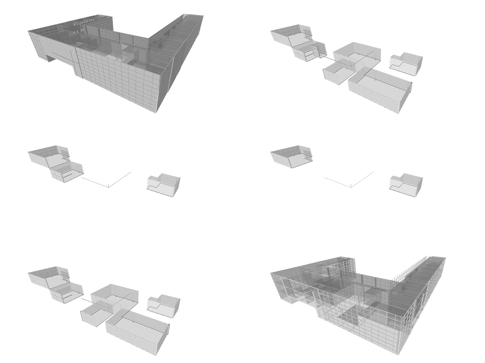
The principal function of the Dynamo definition was to query exterior wall geometry from the model based on a room number and perform material takeoffs, directional composition, and visual analysis.

OBJECTIVES: Target specific rooms in the Revit model by Room Number, isolate the exterior Wall/Window elements specific to that room, calculate total area of exterior facade for each Room, understand composition of vision to solid materials, and ass…

OBJECTIVES: Target specific rooms in the Revit model by Room Number, isolate the exterior Wall/Window elements specific to that room, calculate total area of exterior facade for each Room, understand composition of vision to solid materials, and assist with code calculations such as light & ventilation.

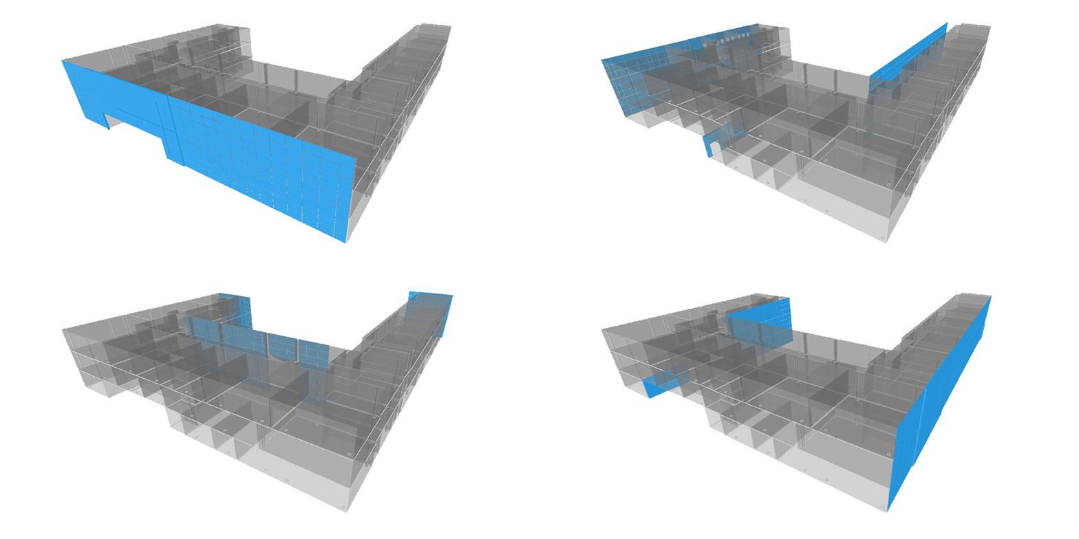
OBJECTIVES: Query all exterior Wall elements, use the underlying geometry to determine direction of each wall, sort walls by cardinal directions or bespoke orientation system, and calculate proportion of facade areas for each direction.

OBJECTIVES: Query all exterior Wall elements, use the underlying geometry to determine direction of each wall, sort walls by cardinal directions or bespoke orientation system, and calculate proportion of facade areas for each direction.

OBJECTIVE: Color specific items for analysis, visual clarity, and storytelling

OBJECTIVE: Color specific items for analysis, visual clarity, and storytelling

The live demonstration was recorded for your viewing pleasure. You may notice the video starts a little late due to technical difficulties but no significant content was missed. Presentation slides and the Dynamo file can be accessed HERE.

Even with a rush towards the end, I was able to successfully make it through all the content. I appreciate the audience being super receptive and patient given the hands-off format. And a very special thank you Timon Hazell, John Schippers, and Dana De Fillippi for the opportunity.

DynamoDC audience

DynamoDC audience

Kyle's "home studio" setup

Kyle's "home studio" setup

The other day I received a surprise t-shirt in the mail as a thank-you, I will wear it with pride!

Image 5_DynamoDC t-shirt.jpg

Facades+ Boston - Visual Programming with Dynamo Workshop

Originally featured on the Tocci Blog, I recap my recent experience co-leading a Dynamo workshop at this year's Facades+ one-day conference in Boston...

Last week I attended and presented at this year’s Facades+ Boston event — a one-day symposium and trade show focused on the importance of high performance envelope design in the AEC Industry.

SYMPOSIUM:

The first half of the day featured three engaging panel discussions.

Panel 1 – Expanding the Envelope: Generating Urban Data for Responsive Design:
This group of panelists urged the importance of data, tech innovation, and digital equity in the Boston built environment. Capturing data for many city metrics helps reveal trends and provide insight for a prosperous and safer tomorrow.

Panel 2 – Modernist Performance Retrofits:
One presentation in architectural detailing for a historical retrofit project provided an intriguing contrast against a second presentation about examining materials and fenestration details to identify high-performing wall assemblies at different price-points. While one project carefully considered the aesthetic ramifications of their intervention, the other team thoroughly emphasized performance.

Panel 3 – Making Space for Bostonians:

Place-making is an essential consideration in urban design and these three panelists discussed the role that strategic programming, structural and material innovation, and inviting public space has played in creating thriving districts in the city of Boston.

VISUAL PROGRAMMING WITH DYNAMO WORKSHOP:

Colin McCrone and I led an afternoon workshop that demonstrated the usefulness of visual programming for Revit in facade design and analysis workflows. Our workshop kicked off with an introduction to the concepts of computational design, migration across various software platforms, and examples of how the tools are being used in the industry today.

After providing an overview of the interface, terminology, functions, and features, the first exercise tackled one of Revit’s most temperamental elements – curtain wall. Modifying curtain wall requires many sequential clicks to adjust overall size, mullion spacing, and exchanging pinned panels, mullions, and doors. Dynamo provides the capability to query information from the model, target specific items, and batch alter them as needed. The accompaniment of math and logic adds further analysis and opportunities for customization to the process.

TBC blog_KM Facades+_1.jpg

For the final portion of the workshop, we highlighted three panelization processes that demonstrate the geometric design potential of Dynamo. The first used pixel brightness from an image to swap out panels by color and generate a mosaic interpretation.

The second read point coordinate data from an excel spreadsheet to place 4-point adaptive curtain wall panels in a curvilinear wall configuration.

TBC blog_KM Facades+_3.jpg

Lastly, the third utilized the Revit Sun Path tool to analyze solar gain on each panel of a wall surface and colorize the panels from least to most exposure.

TBC blog_KM Facades+_4.jpg

Overall the experience was a huge success and we both thoroughly enjoyed sharing our knowledge with the 20 or so members of the Boston AEC community who attended our workshop.

If you would like to learn more about Dynamo, the June gathering of the Dynamo-litia Boston user group will feature a brief recap of the Facades+ workshop and more in-depth presentations of how Dynamo is being used in practice.

More about Facades+ Boston

Design Space Exploration with Dynamo


One of the most challenging aspects of the architectural design process is determining how to organize form to fit an overall parti. Facing endless possible geometric configurations, making sequential alterations towards a fitting result can be difficult without a means to measure suitability. During the initial phases of design research, an architect gathers essential information such as program requirements to meet a clients needs, zoning and code information for a provided site, environmental and material influences, and aesthetic preferences. These assets serve as the foundation for a constraints based design approach where parameters can be assigned in an effort to influence and control form.

Constraints in design are rules or vocabularies that influence form through the design process. An inherent feature of the architectural process is that design must be performed within a set of given parameters. Parameters help to focus the scope of an architect by narrowing the range forms and formal relationships may take within a design solution... Constraint based design takes the parameters associated with a design problem and links them to the attributes of the formal components and relationships of a solution. (Dustin Eggink, http://goo.gl/EktbQ1 )

Dynamo is an ideal platform for constraints based design because the visual programming environment allows you build a parametric model that can be quickly adjusted with changes to input values.

Once you have a functioning Dynamo definition, all of the nodes can be consolidated into one Custom Node by dragging a selection window over everything and going to Edit > Create Node From Selection. This will transition everything to the custom node editing mode -- you can always tell when you are in this mode because the background is yellow.

To create a custom node, the first step is to give it a name, description of what it does, and category (where it will be saved in the Library). All of the input number blocks (far left side) must be swapped out for Input nodes, generally named for the variable they represent. Output nodes also need to be added after the final nodes in the definition (far right side) that are providing the finalized geometry. When these steps are complete, save the node. Back in the Dynamo node space -- also known as the canvas -- number sliders can be added to the newly-created custom node. It is helpful to click the down arrow on the left side of the node to set the minimum, maximum, and step interval because large numbers can take awhile to process or crash Dynamo while zeros will often create null values and turn the majority of your definition yellow with warnings. Now you have a fully parametric custom node that allows you to explore a range of formal configurations with the simple adjustment of number sliders.

Developing custom nodes for form making allows for use with the Dynamo Customizer -- a web-based viewer currently in beta for viewing and interacting with Dynamo models real-time. This platform has a lot of potential for sharing designs in the future and allowing colleagues or clients to experiment with their own manipulations of the design.

Check out this example for the twisting tower here: Dynamo Customizer - Twisting Tower.
DISCLAIMER: you will have to request Beta access and sign in with your Autodesk ID to view this. For step-by-step instructions, visit: http://dynamobim.org/dynamo-customizer-beta-now-available/.

After guiding parameters have been established, a design space can be generated for testing all possible variations of a few select variables of a design. Design space exploration is a concept involving a virtual -- or non physical -- space of possible design outcomes. This allows the designer to simultaneously see a wide range of options and extract only those that satisfy pre-determined criteria of fitness.

The core essence of this workflow is the use of Cartesian product which facilitates comparison of all possible pairings of variables. This mathematic operation can be understood as an array of combinations between x, y, z and 1, 2, 3 (below left) or as a slope graph of all possible correlations between the two lists of variables (below right).

Using the List.CartesianProduct node calculates all possible combinations of the number range values however all of the geometry is instantiated in Dynamo at the origin point, making it appear that only one object was created even though the count shows 132 (below left). Thanks to Zach Kron and the Design Options Layout node from the Buildz package, the nested list clusters of geometric objects are arrayed according to the Grid Size spacing value (below right). Using list management logic -- such as List.Transpose, List.Map with List.Transpose, etc. -- before the Design Options Layout node will re-arrange the list structure and result in different compositions of objects.

To set up a design space in Dynamo, the inputs to the custom node are fixed values. Whichever variables that you want to test must be left empty on the custom node and number ranges are connected to the List.CartesianProduct node. The number of list inputs in List.CartesianProduct must match the number of inputs left open on the custom node. It is also important to note that the list order for the number ranges in the List.CartesianProduct node must correspond to the same order of inputs in the custom node. The total number of values from each number range will not only determine the scale and form of the resultant geometry but count of values in each list will determine the overall size and shape of arrayed objects -- this is critical to remember because an excessive number of input values may take several minutes to process or potentially crash Dynamo. After the ranges of values have been set up, the List.CartesianProduct node is connected to the Design Options Layout node which arrays all possible combinations in 3D space. Depending on the geometry being tested, the Grid Size input determines the spacing between objects. When everything is connected correctly, Dynamo will display an array of forms which can be altered by changing the number range inputs and re-running the definition. If Dynamo crashes, geometry disappears, or there is an insufficient amount of variation in the forms, continue to calibrate the number ranges and explore the limitations of the parameters in your custom node.

A successful design space arrays all possible options along two or more axis utilizing the concept of dimensionality. Design space is theoretically unlimited, however the visualization of the virtual design space is limited to the constraints of graphic representation. Color can be added to provide visual differentiation of a third dimensions such as the analysis of generated outcomes, or could represent any of the associated properties of variables. Criteria for evaluation of fitness refers to the means by which the best solution is determined.

For example, a calculation of height of twisting tower forms can be colorized on minimum to maximum gradient (below left). Another representational technique is selective omission or hierarchical modifications to the representation (below right).

Ultimately design space and its subsequent representation is nothing more than a tool, designers still have to make decisions. Design space should function as a method of exploration to make informed, confident, substaintiated decisions.


Portions of this blog post were developed in collaboration with Jamie Farrell for our course Advanced Revit and Computational Workflows taught at the Boston Architectural College.

Converting Space Planning Families to Revit Room Elements


A few weeks ago at the, Dynamo-litia Boston meeting a fantastic question was raised:

After using the space planning objects for programming in Revit, what happens when you need to transition that information to rooms?

This poses a legitimate challenge because the space planning objects are families and the information associated needs to be converted rooms - fundamentally different Revit elements.

Just days after the Dynamo-litia meeting I was presented with the opportunity to transform a Revit model full of intricately-arranged space planning objects across multiple Levels into Revit room elements. With some effort in Dynamo, I found a way to extract the name, department, and other parameters from each space planning object and generate Revit rooms in exactly the same spot with corresponding information.

Areas to Rooms_definition.png

Using this workflow, 639 programming families became Revit rooms in just under 90 seconds.

The Dynamo definition collects all instances of the Space Planning families in the model, groups them by Level, and locates the centroid of each. Using the Tool.CreateRoomAtPointAndLevel from the package Steamnodes, a room is placed at each centroid in the list with their associated levels.

The one caveat to successful conversion is taking the time to model Revit walls between the space planning objects. Consistency in setting up walls between objects and maintaining thorough parameter information within the objects will eliminate the possibility of creating Not Enclosed or Redundant rooms. Worst case, if rooms are overlapping within the same enclosed area after running Dynamo, you know that the centroid of the room is at the center point of the Space Planning family and you can add additional walls between those centroids to create separation between room elements.

The last step is to remove or hide the visibility of the space planning objects from the model and then you can perform Tag by Category to tag all rooms on each floor.